 ANTENNA PROJECTS
·
·
·
·
·
|
Simple VHF/UHF Ground Plane antennas for under $20 |
These antennas have appeared in numerous publications over the years, including the ARRL Antenna Book, and are only limited by your imagination as to their potential uses. Excellent for local repeater work, APRS, Field Day, Emergency deployment, Stealth installs, the list goes on. They are simple to make, simple to assemble, simple to get the parts for; do you see a pattern here? The most basic design will be shown first, with a few very slick improvements later.
|
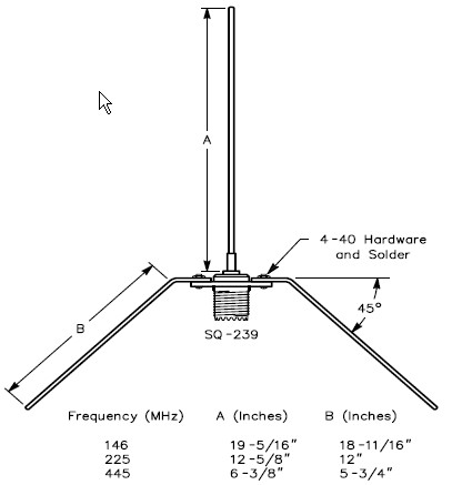 | The entire antenna consists of a panel mount SO-239, some stiff wire (like aluminum welding wire, brazing rod, 12 GA bare copper wire, electric fence wire, etc) or thin brass tubing, some solder, and four 4-40 3/8" long screws, washers, and nuts
Cut the wires to length in accordance with the chart provided for the band you want. You will end up with 5 pieces of wire, 4 the same length (radials) and one slightly longer (driven element). Use a good high wattage soldering iron to tin one end of the driven element
HINT:Cut your radials extra long, mount them on the SO-239, mark the point to start the bend, remove the radials, make the 45deg bend, remount them, then measure and trim to length. When tuning for lowest SWR, remember that the angle of the radials affects the value, so feel free to adjust them anywhere between 30 and 45 deg for best reading. Also, if tubing is used, one end of each radial can be soldered to a ring terminal or hammered flat and drilled |
|
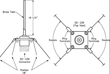 | There are several ways to attach the radials:
- Bend the wire through the corner hole and solder in place — Requires a lot of heat, no longer removable for transport but better electrical connection
- Use a pair of needle nose pliers to fashion one end into a tight loop just big enough for the 4-40 screws to get through — Takes a little work, can loosen over time [use split washers for extra tension], but no soldering
- Solder (or crimp) ring terminals on one end — clean, professional looking, but may break over time with repeat bending
Notice that the length of the radials is measured from the 45 deg bend to the tip, so which ever way you choose, allow for this extra length in your calculations. |
|
So you've got the antenna built, now, how to mount it:
- Bend a loop (or solder a ring terminal) at the top of the driven element, thread some string through it and hoist it up
- Fabricate an "L" shaped bracket that uses two of the 4-40 screws to hold the antenna in place
- Run the feed line up a section of 1/2" PVC with the antenna sitting on top (quick and easy, but not optimum for prolonged exposure to the elements)
- Use the method above, but aquire a PVC end cap, cut slits in four locations to allow the radials to slip through and drill a hole in the top center large enough to allow the driven element through. Cap can be held in place with small sheet metal screws or a pipe clamp. A dab of outdoor sealant around the vertical element and it should be pretty weather resistant
- Use a pipe cap as above, but drill four holes to mount the SO-239 directly to the pipe cap
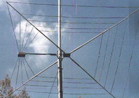
- Or take a look at what KC0YNR did
|
|
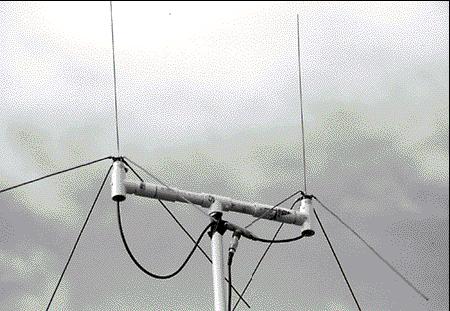
| How about over 6db of gain and a F/B ratio of just under 40db? Build two identical antennas and mount them on a T shaped PVC assembly with a simple coax phasing harness for a phased array. Two ground planes fed 90deg out of phase and spaced 1/4 wavelength apart will exhibit about 4.75db of gain. Not bad! But feed them 135deg out and your gain will increase to over 6db. It will exhibit significant directionality and can be turned with a very simple rotator, and with a much smaller turining radius than a similar yagi (less than 40") |
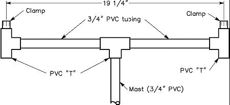 |
"The boom is constructed from schedule-40 PVC tubing (see Figure 2). Take care to assemble it precisely. It's important to maintain the quarter-wavelength spacing between the ground planes"
You'll need:
- 2 Lengths of 3/4-inch diameter PVC tubing 81/4 inches long
- 3 3/4-inch PVC Ts
- 2 Lengths of 3/4-inch diameter PVC tubing 2 inches long
- 1 Tubing cutter (optional)
- 1 Can "purple primer" PVC cement
- 2 1-inch diameter stainless-steel hose clamps
|
|
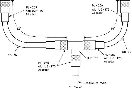 | Detail of the phasing harness. Measurements are critical. Direction of radiation will be toward the antenna connected to the longer line. |
|
 | The phasing harness can be attached to the mast with wire ties, or a plastic junction box (like the one used in the 4BTV SO-239 mod) can be mounted on the mast to house the "T" assembly and protect it from the elements
For complete details on the construction of this phased array, see the ARRL Antenna Book or download the PDF reprint of the original QST article [HERE]
For another take on the same idea, take a look at N0AJ's project |
|
ADDITIONAL NOTES:
Have a dual band rig or HT? You can build two "T" masts like the one above, one for a set of 2M antennas, and one for a set of 70cm antennas (scaled to frequency, of course - you will have to recalculate the phasing harness measurements for 70cm) and then stack them, one above the other.
Or, build one "T" mast to mount one 2M GP and one 70 GP, no rotor, no gain, but fed with a 144/440 duplexer mounted in a plastic junction box. Maybe an emergency antenna for a temporary cross band repeater? Like I said, only restricted by your imagination.. |
|
|
|
|