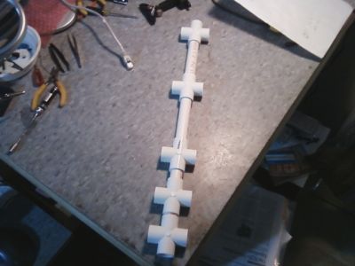
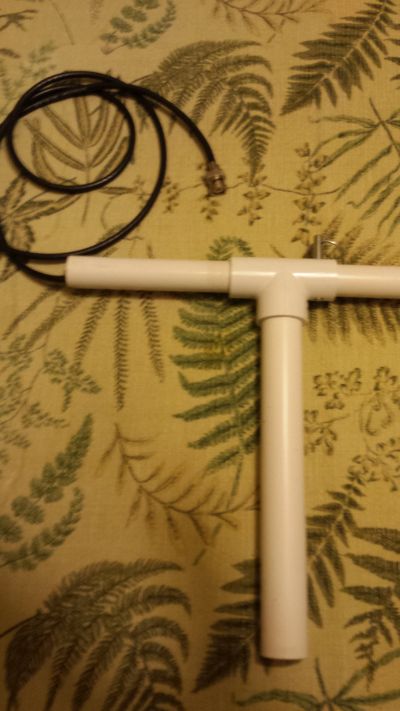
 | PVC cut and temporarily assembled to check measurements of boom length and element spacing adjusted for 440 MHz use.
Tolerances are tighter at the frequency so be sure to take into account the actual depth of the T's in your boom section measurements (about .75").
|
|
| Yagi Dimensions for 440 MHz |
| Reflector (REF) Length | 13.78 |
| Driven (DRI) Element Length | 11.83 |
| 1/2 Driven Element Length | 5.91 |
| Director (DIR) Length | 11.70 |
| REF to DRI element center-to-center length | 2.66 |
| REF PVC length | 1.66 |
| DRI to DIR element center-to-center length | 4.16 |
| DIR PVC length | 3.16 |
| "U" hairpin total length | 1.67 |
|
The critical measurements are the element center to center spacings.
REMEMBER: At this frequency, use 1/2" wide tape, not the 1" wide used for 220 and below. |
|
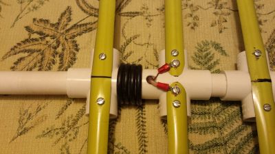 | Close up of the balun, screws, and feed line
Holes were drilled for routing the RG-58 coax through the PVC, wrapped approximately 4 turns, then back into the boom and out the back end. BNC connector was installed after the coax was routed. Lugs were soldered to the ends of the feed line for attaching to the driven elements. The driven elements were sanded clean under the screws,and every thing was assembled as shown. Note the additional set of screws on the driven elements to keep them from twisting.
While the calculations call for a 1.67" hairpin matching wire, this yagi was built without one. The testing continues to determine real world impedences using 1/2" tape and the necessity for a hairpin match at this frequency.
|
|
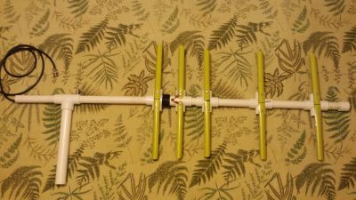 | The finished antenna
Another view of the completed antenna.
Assembled and photographed by Glenn McFarlin, W4ULB
|
|
 | Close up view of the handle
Holes were drilled in the PVC to allow the handle to rotate for vertical horizontal polarization, inserting a pin to lock it in place
Assembled and photographed by Glenn McFarlin, W4ULB
|
|
| Yagi Dimensions for 432 MHz |
| Reflector (REF) Length | 14.04 |
| Driven (DRI) Element Length | 12.04 |
| 1/2 Driven Element Length | 6.02 |
| Director (DIR) Length | 11.92 |
| REF to DRI element center-to-center length | 2.71 |
| REF PVC length | 1.71 |
| DRI to DIR element center-to-center length | 4.24 |
| DIR PVC length | 3.24 |
| "U" hairpin total length | 1.70 |
|
In case someone wants to use one of these for SATCOM work |
|
| Yagi Dimensions for 224 MHz |
| Reflector (REF) Length | 27.07 |
| Driven (DRI) Element Length | 23.23 |
| 1/2 Driven Element Length | 11.61 |
| Director (DIR) Length | 22.98 |
| REF to DRI element center-to-center length | 5.23 |
| REF PVC length | 4.23 |
| DRI to DIR element center-to-center length | 8.18 |
| DIR PVC length | 7.18 |
| "U" hairpin total length | 3.27 |
|
Measurements for 224 MHz |