 Mobile Operations
· Mobile HF & VHF/UHF Installations
· Mobile Power Distribution
· Mobile Shack pictures - Show off your ride!
|
W4ULB Mobile Operations 2007-2012 |
|
Shortly after my retirement from the military in 2006, the ARRL announced that it was going to be dropping the code requirement for General and Extra class licenses. I had had my Technician class license since 1992, but never could bring myself to learn the code well enough to pass the test. Even back in the mid-'70s after wearing thin the Novice study guide and getting to where I could easily pass the written exam, I could not bring myself to learn the code.
So, you are thinking, you waited until after they dropped the code requirement and upgraded, right? Nope. In my convoluted mind I now had a challenge that directly effected my ego. I could pass the General test WITH code, just so I could say I did. I dug an old Palm Pilot out of a junk box (this was before smart phones), charged it up, and found a free code study app to use. I studied every chance I had (you should see the looks on people's faces when they hear Morse code coming from a public bathroom stall) and when I felt confident, I took the test and passed with the code! (My wife still shakes her head when I tell that story, mumbling something about my ego and how I could have done it years earlier)
So now I had nearly full HF privileges! I had an old Kenwood in the home shack, but a new job that involved 10 hour days and a 40 minute commute each way didn't leave me much time to operate HF. The answer was to operate mobile during commutes and trips out of town. When a friend told me he had a used Icom IC-706MKIIG in excellent condition for sale at a very reasonable price, I couldn't turn it down. Over the next few hamfests I purchased all the remaining items I needed to complete my mobile shack, like a quad mag mount, a Heil Traveler® single ear headset-boom mic, a set of HamStick® antennas covering 80m-6m, an LDG 1000+ auto-tuner, and various cables, connectors, and adapters.
My plan was to install a Yaesu FT-8800 VHF/UHF FM dual band for local repeaters, an Icom IC-706MKII-G for HF/6M and VHF/UHF SSB (contesting), and a small Midland 11 meter rig for monitoring highway traffic on long trips. The following set of pictures will show how I finally completed the initial install in my 2001 Nissan Frontier pickup.
(Click on any picture to open a larger one)
|
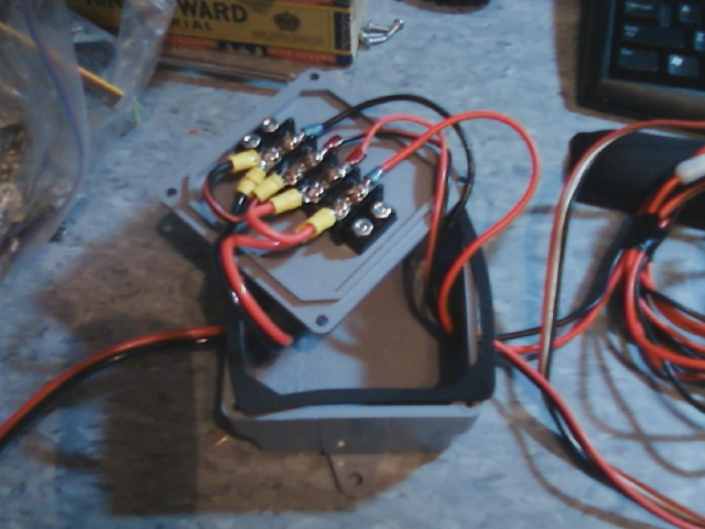
My first concern was providing power to all these radios and accessories. I'm a bit OCD about loose wires and sloppy installations, so I wanted a clean, organized way to distribute a single feed directly from the battery.
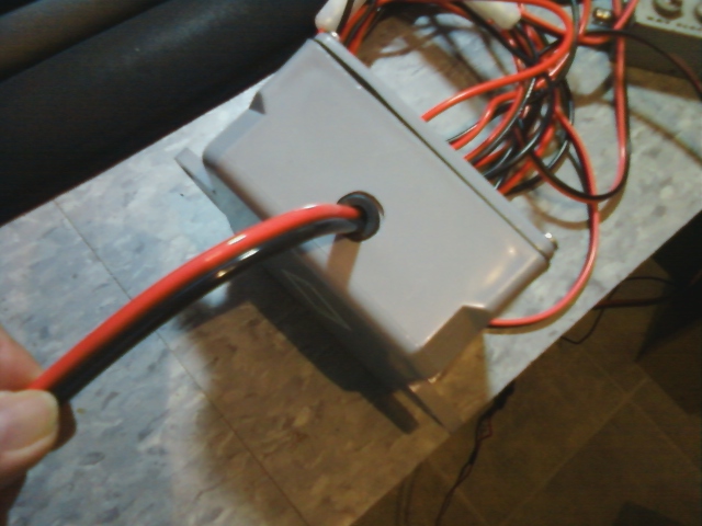
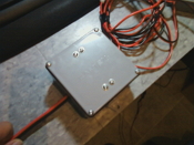
After researching retail distribution solutions, my tight wad nature decided it would be much cheaper to do it myself. A visit to the local hardware retailer gave me the idea to use a plastic electrical junction box. I drilled a hole on two opposing sides, one for the DC supply cable to enter, and one for all the DC lines from the equipment. I drilled them large enough to insert rubber grommets to help hold the wires and prevent chafing.
I mounted a terminal strip to the cover with the positive side of the DC supply attached to two rows and the negative line to the other two. The DC lines for the equipment were attached to the appropriate rows, with parallel jumpers used to distribute the power. As with anything else, make sure both your DC lines are fused! |

|
|

|
|
|
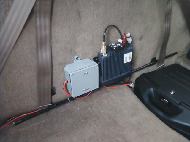
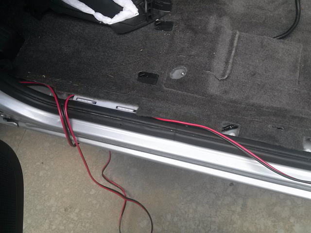
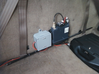
The initial install was just the power distribution box and the Yaesu FT-8800. These were mounted directly to the back wall of the cab using sheet metal screws. In this particular vehicle, the seats and center console were very easy to remove and the carpet lifted easily.
The door channel strips were just snapped in place so routing of the wires from the engine compartment to the radios was pretty straight forward. Whatever way you find easiest to route the power cables, look for possible chafing points and reinforce the cables there with shrink wrap or electricians tape. Radio head extension cables can be routed directly under the carpet to a location close to the head mounting point. (The wire for the CB's remote speaker was also routed here) |
|

|
|
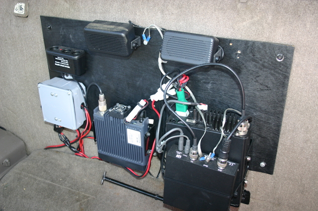
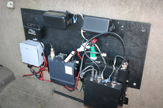
As the list of acquired equipment grew,it was clear that direct mounting to the cab wall was not practical. So I decided to use a piece of 1/4 inch plywood painted black, to mount every thing I wanted, including radios, power distribution, speakers, and extra 12VDC power sockets. This particular year the small KingCab jump seats were mounted to the side walls vice the rear wall (like they are in the 2012 model..) so their removal was not required.
All the radio brackets and other items were first laid out on the board to determine best cable routing, ground points, and clearance between radios (the LDG auto-tuner was mounted to the top of the IC-706 using hook & pile strips and wire ties). Brackets and any items requiring through-board machine screws were mounted first, then the board was mounted to the rear cab wall using sheet metal screws in as many of the earlier drilled holes as possible. The power distribution box was mounted in the lower left corner using wood screws. All ground straps were neatly routed to a single point, a screw driven in to the metal of the rear cab wall near the top of the board. The radios were mounted to their brackets, then power wires and extension cables were connected.
We're about 1/3 of the way there! |
|
|
|
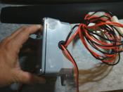
| Here is a close up of the power distribution box, where you can see the snap-on ferrite cores and Anderson Power Poles. Main DC supply line from the battery enters on the left, power wires for the radios exit the right side and bottom. PowerPoles were used to allow for standardization of DC connections and quick change out of radios, if necessary. (My home radio shack uses them on all DC power connections as well) |

|
|
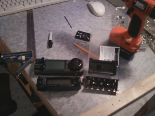
I chose a $20 LidoMount 18" goose neck seat bolt radio mount for mounting the control heads. This would place the controls within easy reach while driving, required no drilling, and allowed the mount to be swivelled toward the passenger seat. Only problem was, the radio head mounting bracket plate that comes with the mount was only designed to hold one head, and I needed to mount two. I found some possible retail solutions for this, but they all seemed a bit expensive. So, a quick trip to the hardware store and a couple of dollars later, I had a small sheet of clear acrylic, large enough to make several adapter plates (it looks cloudy in the pictures because it comes with a protective coating that peels off later). I wanted to end up with the FT-8800 on top and the IC-706MKIIG on the bottom.
I positioned the FT-8800's radio head with mounting bracket attached near one edge of the acrylic sheet so that when the head was in its normal operating position, the sheet of acrylic extended below it. Once it was centered and level, I noted the FT-8800's mounting bracket position, removed the radio head, repositioned the bracket, then marked its two mounting holes for drilling. I drilled out the holes and used short 6/32 hardware with split washers to mount the bracket. I next did the same with the head and bracket for the 706, making sure I gave myself enough room between the two heads. Watch the orientation of both radio brackets to make sure that when you mount them, the control heads are not upside down.
Also, pay attention to the mounting holes (and orientation) of the LidoMount plate to make sure the position of either radio bracket will not interfere with its mounting screws. The Lido plate has two tab slots on the back for mounting either vertically or horizontally to the goose neck. Attach the Lido plate for horizontal orientation with the slot up, mounting screws from the front, through the acrylic and out the back side of the plate. There are recesses on the back of the Lido plate for the supplied nuts. Don't tighten any of the screws down too much or you will crack the acrylic. |
|
|
|
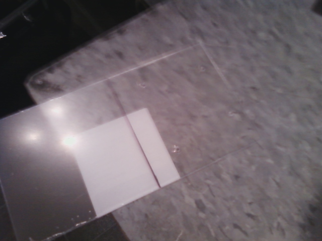
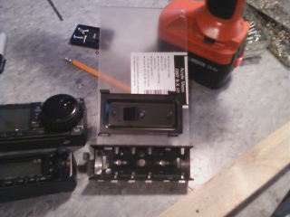
| Once the acrylic has been drilled and the overall size determined, mark the excess to be removed. Using a straight edge and a box cutter, score the acrylic several times to make a deep cut. Holding the drilled portion down on a flat surface with the scored line on top, along the edge of a table or counter, push down gently on the excess section to snap it off (hopefully along the line you scored). In the picture the drilled section is to the right of the line. |

|
|
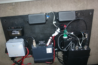
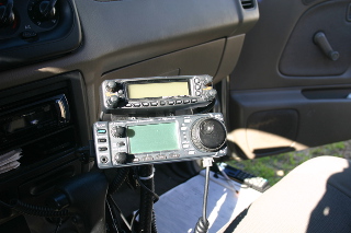
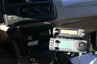
| Here are several views of the final set up. It turned out even better than I though it would! |
|
|
| A wider view of the set up. You can see the mic clip for the FT-8800 mounted to the dash (this one was the old fashioned, screw in metal type, but you can get plastic clips with strong 3M™ adhesive on the back for about $5 if you don't want to make a hole). The mic holder for the IC-706MKIIG is mounted with a wire tie to the goose neck. |

|
|
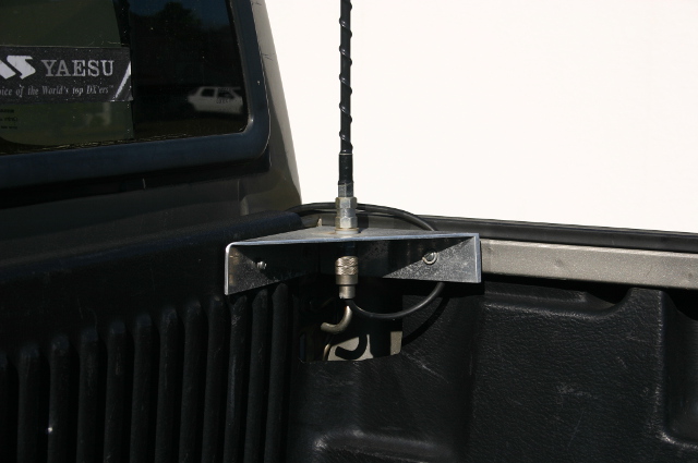
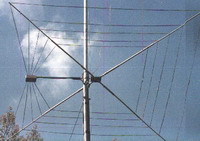
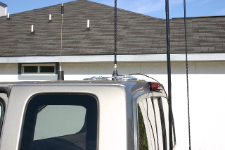
I ended up mounting 4 antennas; An NMO mount forward center of the cab roof for a dual band VHF/UHF (just forward of the NMO mount is a mag-mount Sirius/XM™ puck antenna), a quad-mag mount aft center for HF HamStick® type whips, and two truck bed corner triangle mounts for a 6 meter whip and an 11 meter whip. All coax (except the NMO) was routed under the cab and entered through a large rubber grommet/boot all ready present on the passenger side under the carpet (just behind to passenger seat). It was easier to run the coax with no PL-259 connectors on the ends then solder them on after, but with some effort and pliers, they can be pushed/pulled through the rubber boot.
The aluminium truck bed corner mounts sell for about $10-15 at hamfests or online and can be set up for SO-239, 3/8-24 stud, and several other connection methods depending on the antennas you have or want to use. The mounting hardware is sold separately from the mounts. I specifically purchased antennas and hardware for this project that used 3/8-24 studs. After drilling holes into the bed rail for the bracket mounting bolts, I used spring washers under the retaining nuts to prevent loosening from vehicle vibration. In the first picture you can see one of the brackets in place. In the second, you can see all four antennas. |

|
|
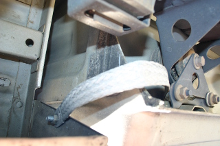
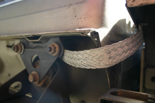
Once I had everything installed and properly tucked away, I went for a ride up the interstate to test it all. VHF/UHF worked like a charm with good audio reports. The CB did as well, but I did notice some alternator noise. Uh oh, the dreaded EMI (Electromagnetic Interference). Firing up the 706MKIIG on 20 meters confirmed my suspicions. I had a bunch of EMI to contend with, resulting in a noise floor sometimes as high as S-9. Also, when I transmitted I could hear my audio come through the stereo speakers. Once I returned home, I started clamping ferrite chokes on every associated cable I could find, especially remote head, microphone, and coax cables. This helped, but wasn't enough. A trip to the local auto parts store netted me some large grounding straps with lugs already attached, and several muffler clamps. Under the truck, employing existing bolts, I used the straps to electrically bond together the bed to the cab, the cab to the frame, and, in several places along its length, the exhaust pipe to the frame.
There are dozens of in-depth discussions on the web about how and why to do this, so I won't go into a long dissertation. Suffice it to say that on most vehicles today, major body parts are rubber isolated from the frame in an effort to minimize road noise. Unfortunately, the frame is the main electrical ground, so bonding these major body parts to the frame can go a long way toward reducing local electrical noise (the exhaust pipe can even act like an antenna of sorts and amplify the noise!), and consequently, your HF noise floor.
I started with a couple of well placed chokes and straps then checked to see what effect it had, adding more as necessary. Results may vary for other vehicles (to anyone trying to do this with an electric car, you have my sympathies). In the end, my efforts helped greatly and now my normal (vehicle induced) noise floor is about 1-2 S-units. |
|
|
On a truck like mine, bonding the major body parts together also helped increase the overall ground plane of all my antennas, resulting in much better efficiency (the whips are half-wave length radiators so the ground plane is the other half!).
I'm not sure if it is the location of the HF whip high up and center of the roof (an unobstructed position is always the best) or the increased ground plane (or both) that makes it work so well, but now that some time has passed and I have completed hundreds of mobile world wide HF QSO's, I am thrilled at how often I can bust through huge DX pileups with just 100 watts. Driving around the far south-east corner of Georgia, I have received excellent signal reports from South Africa, Australia, Kuwait, Eastern Europe, and many more DX locations (road noise picked up by the headset mic is still a problem, but I am working on building an in-line microphone noise gate to reduce it - that will be a different project page). |
|
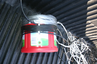
Remember I mentioned hearing my signal through the stereo speakers? Using an empty plastic coffee container, I wrapped 8 turns of the excess coax from the quad-mag mount around it (making sure none of them crossed over each other) and secured them in place with wire ties. You can see the result in this picture. Between this choke-balun and the ferrite cores, I don't hear myself any more!
But the stereo is still a useful part of this system! Here is a little trick: I plug one end of a mono audio cable into the 706's headphone jack and plug the other end (with a mono-to-stereo adapter on it) into the AUX jack on the stereo. That way, I can hear the rigs audio loud and clear through the stereo. Very nice when I just want to enjoy some shortwave broadcasts on a long trip! |
|
|
|
I hope someone with a similar project finds this useful! Thanks for reading, 73 de W4ULB
UPDATE 2012: I have traded in my trusty 2001 model (with 210,000 miles on it) for a shiny new 2012 model. I will post a write up of that install soon!
|
|
|
|